

In our prior discussions, we delved into the concept of mold sprues as a fundamental component of the feeding system. Today, let's explore the next structures within this system – the mold runner and sub-runner. Similar to sprues, many mold designers often overlook the structures of runners and sub-runners due to their standardized and relatively straightforward design criteria. However, to become an elite mold designer capable of delivering top-tier molds that satisfy clients, mastering every detail is essential.
What Are Runners and Sub-Runners?
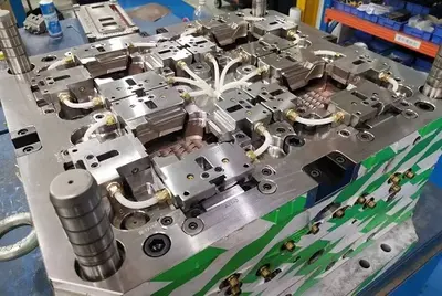
First, let's revisit the entire feeding system for context. The feeding system consists of structures that transport molten plastic from the injection molding machine's barrel into the mold cavity. After the molten plastic is ejected from the machine's nozzle, it travels through the sprue, runner, sub-runner, and gate before filling the cavity to form the plastic part.
Thus, the runner serves as the passage between the sprue and the gate, acting as a transitional section for molten plastic flow from the sprue to the cavity. It redirects the melt smoothly and, in multi-cavity molds, distributes the melt to each cavity. Notably, single-cavity molds typically exclude runners, depending on cavity layout.
Design Guidelines for Mold Runners
Cross-Sectional Shapes of Mold Runners
Rectangular Cross-Section:
Rectangular runners are widely used for their manufacturing simplicity, straightforward tooling design, and uniform flow distribution. Dimensions can be adjusted based on specific part-molding requirements.
Trapezoidal Cross-Section:
Trapezoidal runners promote optimal flow and reduce pressure drop, enhancing cavity filling. The wider end connects to the sprue, while the narrower end links to the gate.
Circular Cross-Section:
Circular runners offer excellent flow characteristics, ideal for complex geometries or balanced flow needs. Diameter selection must balance flow efficiency and pressure loss.
Semi-Circular Cross-Section:
Semi-circular runners feature a half-circle profile, minimizing pressure drop and ensuring mooth flow. Diameter sizing depends on specific molding process requirements.
U-Shaped Cross-Section:
U-shaped runners have a curved bottom and vertical walls, facilitating material flow and easy separation from the molded part. This design is preferred for bottom-gated parts or when runner removal is critical.
The choice of cross-sectional shape hinges on material properties, part design, mold layout, and production needs.
Sizing of Mold Runners and Sub-Runners
Runner dimensions depend on factors like product design, mold structure, and molding process requirements. While part size and wall thickness influence design, larger cross-sections don’t inherently improve filling; optimal design is determined by material flow behavior, geometry, gate location, and process parameters.
Notably, runner length doesn’t directly affect plastic viscosity, which is governed by material properties and processing conditions. A well-designed runner system significantly impacts molding efficiency and part quality.
Arrangement of Mold Runners and Sub-Runners
Balanced Runner System:
Runners from the sprue to each cavity have equal length, shape, and cross-section, ensuring thermal and flow balance for consistent part quality.
Unbalanced Runner System:
Allows plastic to enter cavities at different times, potentially causing filling variations. Advantages include compact cavity layouts, reduced template size, and shorter runner lengths.
Both systems must ensure cavity symmetry with the mold base center to align the projected center of cavities/runners with the injection machine’s clamping force center, preventing tilting moments during injection molding production process. Balanced systems are ideal for multi-cavity molds requiring uniform product quality.
Design Principles for Runners and Sub-Runners
Ensure molten plastic enters the cavity rapidly via the shortest path with minimal heat and pressure loss.
Enable simultaneous cavity filling from multiple gates under identical temperature and pressure conditions.
While larger cross-sections aid molding and packing, prioritize smaller areas to reduce plastic consumption and cooling time.
Minimize the surface area-to-volume ratio in runners to conserve material and expedite cooling.
Maintain runner surface roughness (typically Ra 1.6 μm) to prevent cold material drag into the cavity.
Connect runners and gates with slopes and arcs to enhance flow, reduce resistance, and facilitate filling.
Is a Sub-Runner Necessary in Mold Design?
Sub-runners are used to divide molten plastic flow into different directions within the cavity, aiding filling in complex or multi-cavity molds. However, simple runner designs may suffice for basic applications. The decision to include a sub-runner depends on part design complexity and molding process requirements.


 Call us on:
  Email Us:
  1st Floor, Block1, No.3 Beiting Road, Houting Community, ShaJing Street, Bao'An District, Shenzhen City, Guangdong Province, China
  English
 Deutsch
 italiano
 русский
 français
 română
 العربية
 Español
 Polska
 日本語
日本語 한국어
한국어