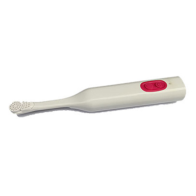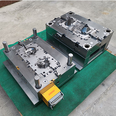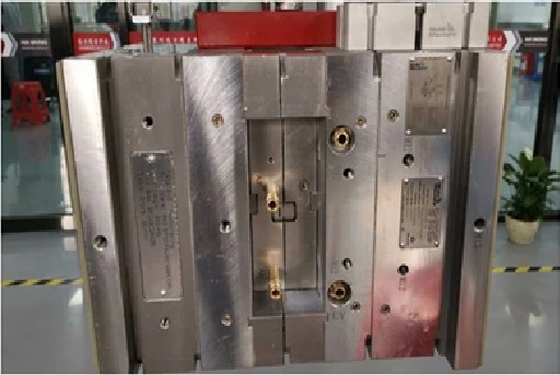
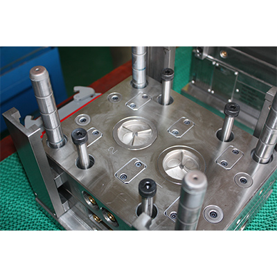
Mould Name: 3 Plate Insert Mould
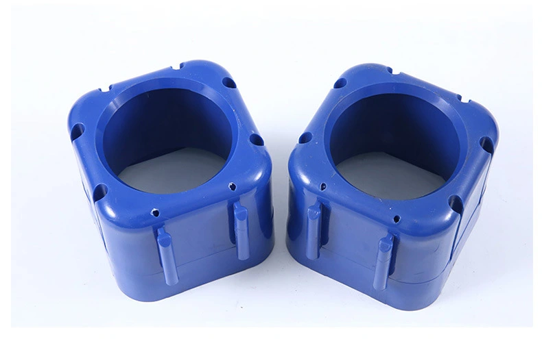
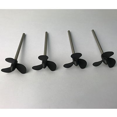
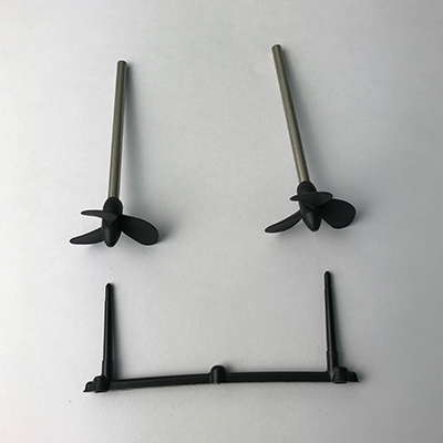
Part Material: PBT GF15
Product Size: ф34.9x82.29
Product Description: Mischschraube kpl
Mould Cavity: 2 Cavities
Mould Size: 250*230*350 MM
Mould Cavity Steel: 2343 ESR
Mould Injection System: 3-Plate point gate
Mould Ejection System: Round ejector
Mould Cycle Time: 28's
Mould Life Cycle: 500,000
Lead Time: 45 working days
Mould Features: insert molding
3 plate mould is also called pinpoint gate mould.
There are two parting surfaces to divide the mold into three parts. Compared with the two plate molds, the gate plate of three plate mold is added. It is suitable for the molds that do not allow gate marks around the product. This type of mold uses a pointed gate, so it is called pinpoint gate mold.
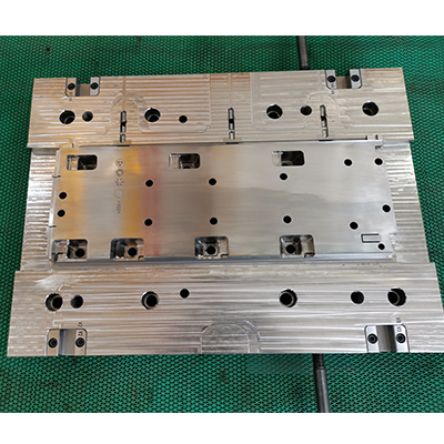
The mold opening process: the three-plate mold has two parting processes, the first between the stripping plate and the cavity plate, and the second time between the cavity plate and the core plate. When the core side is pulled by the injection molding machine, as the A and B plate are equipped with a latch lock, and there is no connection or obstruction between the stripping plate and the A plate (in most cases, the pull rod is also equipped with a spring) At this time, the stripping plate is first separated from the cavity plate by the pulling force, and the cavity plate moves backward with the core plate. When moving to the set distance, it is blocked by the pull rod limiting block, because the A plate continues to move with the injection molding machine. Therefore, the pull rod is also driven, and the pull rod drives the stripping plate to move to the next set distance and then the pull rod and the cavity plate stops moving.
The injection molding machine continues to move backward, as the pulling force continues to increase, exceeding the locking force of the latch lock, the A plate is separated from the B plate, and stops when the set distance is reached.
The ejector plate drives the ejector mechanism (the ejector pin, the ejector rod, and the lifter) to start the ejection movement, and the finished product is ejected (automatically dropped or removed by the robot).
Clamping process - When there is a pullback mechanism on the ejector plate, the ejector plate is forcibly pulled back by the injection molding machine before clamping.
Under the push of the injection molding machine, the core moves forward to the cavity side, if the ejector plate is not pulled back in advance, the return pin first contacts the cavity plate. Under the reaction force, the ejector plate is returned by the return pin.
The B plate is pressed against the A plate and the stripping plate, and finally completely tight. The nozzle on the injection molding machine is closely fitted with the nozzle bushing on the mold, and the next cycle of injection molding is started.
 Call us on:
  Email Us:
  1st Floor, Block1, No.3 Beiting Road, Houting Community, ShaJing Street, Bao'An District, Shenzhen City, Guangdong Province, China
  English
 Deutsch
 italiano
 русский
 français
 română
 العربية
 Español
 Polska
 日本語
日本語 한국어
한국어 Enquiry