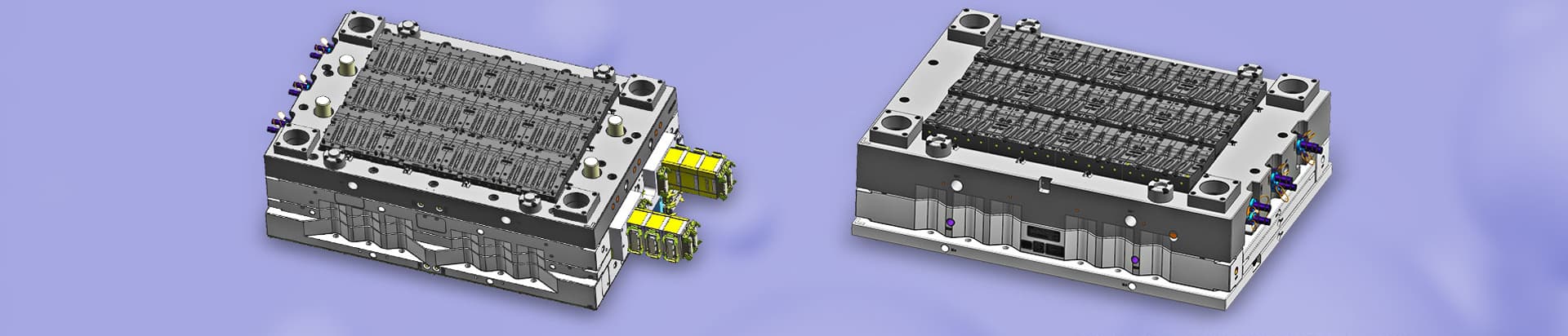
The design and application of hot runner molds rely on eight core factors: material adaptability, system selection, precise temperature control, runner balance, thermal expansion & sealing, cooling isolation, electrical safety, and cost-effectiveness. Full integration with mold structure, injection molding machine parameters, and mass production stability is also essential.
Materials must be matched with suitable nozzle types (open / needle valve) and mold steels: corrosion-resistant and wear-resistant alloys such as H13, molybdenum‑titanium alloy, or powder metallurgy steel. Temperature control must be tight (±0.5–1℃), flow channels free of dead corners, and melt residence time minimized.
Open nozzles: low cost, simple structure; ideal for high-volume, low-cost parts (packaging, home appliances) or non-appearance components.
Needle‑valve gates: no gate marks, precise pressure control; used for high‑precision 3C shells, medical parts, and visible exterior components.
Layout can be single‑point, multi‑point, or custom manifold design.
Key measures include proper thermocouple placement, matched heating power, effective insulation (e.g., 2–3mm air gap or titanium alloy insulation sheet between hot runner plate and mold base), and redundant temperature controller design to prevent overheating, melt degradation, cold slugs, or drool.
runner length difference ≤ 5mm
consistent circular cross‑section
surface roughness Ra ≤ 0.4μm
CAE simulation (Moldflow) is used to optimize gate location and size (typically 0.8–1.2× part wall thickness) and ensure filling time difference ≤ 0.1s, avoiding short‑shot or unbalanced filling.
axial clearance at room temperature approx. 0.025mm
expansion reserve calculated as ΔL = L × α × ΔT (usually 1.5–2× expansion)
precision fitting between nozzle and insert (hardness ≥ 50HRC, diameter tolerance ≤ 0.01mm)
Sealing must withstand ≥ 50MPa using elastic or metal‑to‑metal seals to prevent leakage and damage to heating components.
distance from cooling channels ≥ 5–8mm
local air gaps or insulation boards recommended
This avoids thermal interference, uneven cooling, distortion, or uncontrolled heat loss.
Clear installation, disassembly, and service space must be reserved. Wear parts (hot nozzles) should allow quick replacement to reduce downtime. A safety gap ≥10mm must be maintained between nozzles and moving components (sliders, lifters).
annual volume >50,000 shots (ideally >500,000 for fast payback)
high scrap rates, automation needs, or frequent color changes
Benefits include 10–20% material savings and 20–40% shorter cycle times. Standard components are preferred for shorter lead times and easier maintenance.
Product requirements (appearance / precision)
Resin characteristics
Required output
Available mold space
Budget limit
Then determine nozzle type, manifold layout, and temperature control strategy.




 Call us on:
  Email Us:
  1st Floor, Block1, No.3 Beiting Road, Houting Community, ShaJing Street, Bao'An District, Shenzhen City, Guangdong Province, China
  English
 Deutsch
 italiano
 русский
 français
 română
 العربية
 Español
 Polska
 日本語
日本語 한국어
한국어