

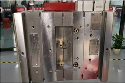
1. After arranging thimble, inserting needle, inclined top, and nozzle, then arrange the water transportation hole to avoid interference with these components;
2. Choose the diameter of the water-carrying hole according to the size of the automobile mould, and control the distance between the good luck water-holes and the distance from the water-carrying hole to the glue position;
3. It is best to make the water-carrying holes vertical, and it is difficult to process oblique holes and spatial angle holes;
4. Try to connect the water-carrying holes in series inside the mold, not outside the mold;
5. The horizontal direction of the water-carrying holes of the front and rear molds of the automobile mold is best to be different, which is conducive to the cooling effect.
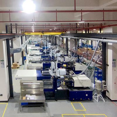
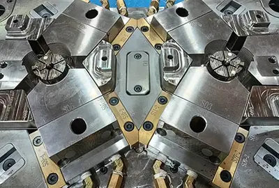
With professional and advanced technologies, Hanking mold provides automobile mould for various vehicles. And here we will introduce to you some knowledge about the principle of the layout of automobile mould support.
1. The support head should not be placed too close to the square iron. It should be placed below the product and near the main rubber inlet. The deformation force of the rear mold of the automobile mold is mainly the injection pressure of the injection molding machine;
2. The distance between the support head and the thimble should be more than 5mm, and the distance between the support head and the support head is about 80-120mm;
3. The diameter of the automobile die support head is 2mm smaller than the unprocessed round bar material; it can be designed as: ¢33, ¢38, ¢43, ¢48, ¢53, ¢58, ¢63, ¢68, ¢73;
4. When designing the support head, try to be as large as possible, but do not need to design a lot, avoid hollowing out the thimble plate, so as to avoid the thimble plate is not strong enough;
The support head layout should be about 25%-30% of the projected area of the thimble plate.

 Call us on:
  Email Us:
  1st Floor, Block1, No.3 Beiting Road, Houting Community, ShaJing Street, Bao'An District, Shenzhen City, Guangdong Province, China
  English
 Deutsch
 italiano
 русский
 français
 română
 العربية
 Español
 Polska
 日本語
日本語 한국어
한국어