The optimal gate location refers to the thickest wall section of the part in injection molding. Its design directly impacts melt flow and molding quality. By rationally setting the gate position and optimizing the filling process, defects can be reduced. This concept is applicable to mold design for various complex parts such as gears, pipe fittings, and cups.
Gate design must adhere to basic principles tailored to part structure, material properties, and molding requirements to ensure molding quality and production efficiency.
Prioritize setting the gate at the thickest wall section of the part to ensure sufficient filling and packing.
Avoid locating the gate near high-stress areas to prevent residual stress concentration.
For long parts (especially those made of reinforced compounds), arrange gates along the longitudinal direction instead of transverse or central positions.
In multi-cavity molds, ensure symmetric distribution of parts and gates relative to the sprue.
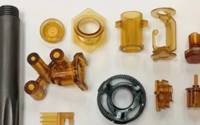
For axially symmetric parts (e.g., gears, disks, blades), use diaphragm gates at the center or multiple gates in three-plate molds to optimize flow characteristics.
For parts with integral hinges, position the gate to keep weld lines away from hinge points; avoid stagnant melt areas near hinges.
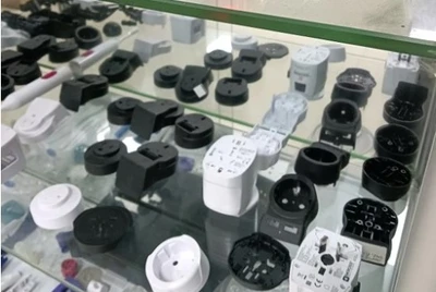
For cup-shaped parts (e.g., small housings, capacitor cups), place the gate near the base to prevent air pockets.
For tubular parts, design the gate to first fill the circumference of one end, then the full length of the tube, avoiding asymmetric melt fronts.
For insert molding (e.g., plastic plugs, soluble cores, metal inserts), ensure molten resin flows around the insert to minimize positional inaccuracies.
For exposed surfaces requiring no visible defects (e.g., gate marks), use sub-gates (tunnel gates) feeding to ejector pins, hidden internally.
For complex parts or multi-cavity molds with varied shapes, minimize temporary stagnation of the melt front during filling.
The above principles do not cover all scenarios. Practical design requires compromises and balance, depending on the complexity of the specific molding process.
Gate location selection must align with multiple requirements, including appearance, functionality, mold processing, and production feasibility.
Minimize visible defects such as gate marks and weld lines, especially for parts with aesthetic demands.
Avoid affecting part performance—e.g., keep gates away from stress-bearing areas (e.g., bearings) to prevent residual stress.
Ensure the gate design is compatible with mold manufacturing, avoiding overly complex structures that increase processing difficulty.
Optimize gate position to reduce uneven shrinkage and warpage of the finished product.
Facilitate easy gate trimming (preferably automated) with minimal residual marks.
Gate location directly influences molding process stability and part performance.
Flow length determines injection pressure, clamping force, and filling completeness. Shorter flow lengths reduce injection pressure and clamping force, improving filling efficiency.
Gate location affects packing pressure magnitude and balance. Proper positioning ensures uniform packing, reducing internal stress.
Gate location must support effective cavity ventilation to avoid air trapping.
Avoid placing gates at weak sections or insert locations to prevent core shaft deflection.
Scientific gate location selection relies on practical techniques combined with part and material characteristics.
Locate the gate at the thickest part to ensure adequate filling and packing.
Thin sections solidify faster than thick ones; insufficient packing causes defects.
Avoid gates at sudden thickness changes to prevent hesitation or short shots.
Central gating provides equal flow lengths in all directions, reducing injection pressure requirements.
Ensures uniform packing pressure, minimizing uneven volume shrinkage.
A gate is a short channel with a small cross-sectional area connecting the runner to the cavity. Its design balances two key factors:
Maximize cross-sectional area and minimize length to reduce pressure loss during melt flow.
Keep the gate narrow to enable rapid solidification and prevent excessive melt backflow.
Opt for a circular cross-section (when possible) and position the gate at the center of the runner.
Gate size is defined by cross-sectional area and length, determined by:
Ensure uniform melt distribution to all cavity areas.
Maintain a consistent and stable melt front throughout the filling process.
Mitigate potential defects: weld lines, bubbles, sink marks, voids, short shots, and jetting.
Prioritize easy, preferably automated, gate removal.
Align gate position with mold structure, part functionality, and appearance requirements.
Gate balancing ensures uniform filling of all cavities, critical for multi-cavity molds (especially with unbalanced runner systems).
Set the size of one gate as a reference.
Calculate the ratio of reference gate size to its corresponding cavity volume.
Apply this ratio to determine sizes for other gates based on their cavity volumes.
Validate and refine through actual test runs.
When plastic flows through the runner, the layer near the mold surface cools and solidifies first. The molten core flows over this solidified layer (plastic is a poor thermal conductor, so the solid layer acts as insulation).
For circular or hexagonal runners, position the gate at the center of the runner cross-section to maximize flow efficiency.
Trapezoidal runners cannot achieve this optimal position, as the gate cannot be centered.
A direct gate feeds melt directly from the sprue to the part, adhering to the finished product after
injection molding.
Leaves a visible gate mark on the part surface, affecting appearance.
Mark size is related to the sprue bushing’s small diameter hole.
Reduce gate mark size by minimizing sprue bushing dimensions (constrained by the machine nozzle diameter).
Maintain a minimum draft angle of 3° for easy demolding.
Shorten sprue bushing length by using an extended machine nozzle.
The gate is the final segment of the injection mold feeding system, connecting the runner to the cavity. Its core functions are:
Deliver molten plastic from the runner into the cavity at maximum speed to ensure full filling.
Rapidly cool and seal after cavity filling to prevent backflow of uncooled melt.
Gate design is influenced by part size, shape, mold structure, injection process conditions, and plastic properties. Aligned with its core functions, the gate should have a small cross-section and short length to maximize flow speed, enable rapid cooling/sealing, facilitate part separation, and minimize residual marks. Key design points include:
Locate gates at thick part sections to ensure full filling (melt flows from thick to thin sections).
Minimize flow length to reduce pressure loss.
Support effective cavity ventilation.
Avoid direct melt impingement into the cavity (prevents vortexes and spiral marks, especially with narrow gates).
Prevent weld lines on visible surfaces; add cold slugs for circular/cylindrical parts at melt meeting points.
Position gates away from slender cores to avoid core deflection from melt impact.
Use multiple gates for large or flat parts to prevent warpage, deformation, and short shots.
Place gates at non-visible locations (e.g., edges, bottom) to preserve appearance.
Determine gate size based on part dimensions, shape, and plastic properties.
Balance gates in multi-cavity molds (along with runner balancing) to ensure simultaneous, uniform filling.


 Call us on:
  Email Us:
  1st Floor, Block1, No.3 Beiting Road, Houting Community, ShaJing Street, Bao'An District, Shenzhen City, Guangdong Province, China
  English
 Deutsch
 italiano
 русский
 français
 română
 العربية
 Español
 Polska
 日本語
日本語 한국어
한국어